
10.25.2007
The Rubik's Cube Subwoofer Goes International!!
The Netherlands:
I Am The Media - Thanks Joery!!
The UK:
DCEMU - Thanks Shrygue!
France:
Thanks to Gizmodo France!
Japan:
Thanks Netallica (Netarika)!!
...and of course Gizmodo Australia!
10.17.2007
10.11.2007
The Beginning...
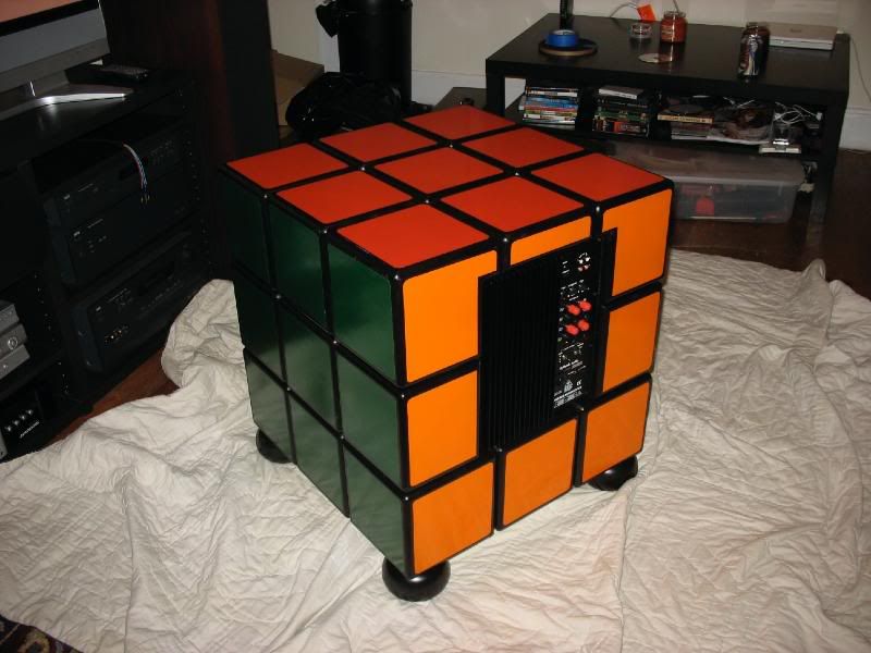
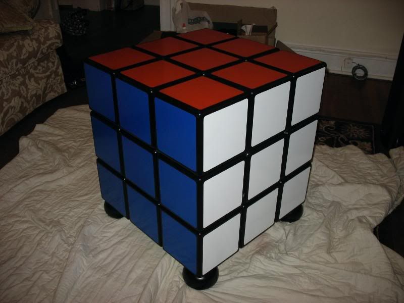
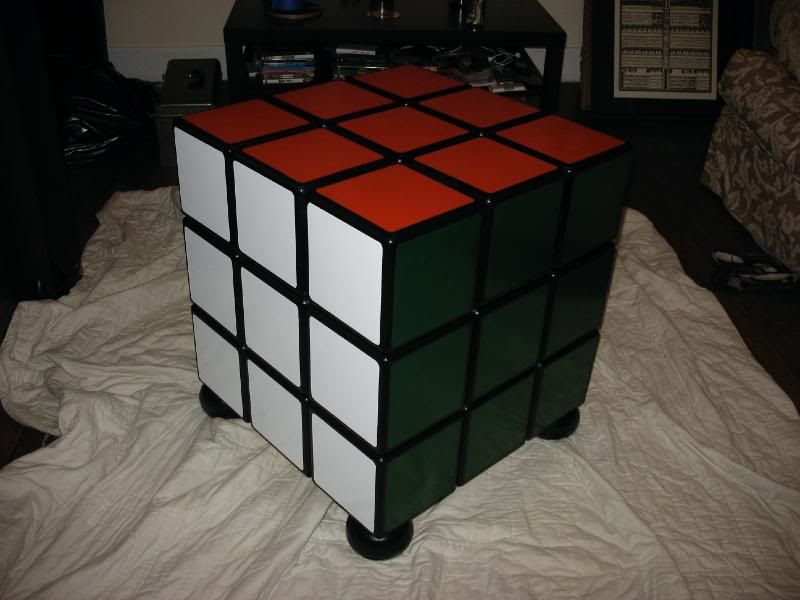
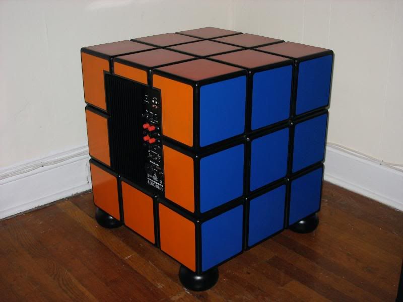
On July 10th 2007 I began making a personal addition to my home theatre's sound system - 80 days later I completed it: the world's first Rubik's Cube subwoofer...
In case you are unfamiliar with subwoofer construction, Brian Steele runs a great site - the DIY Subwoofer Page. On it, you'll find advice, calculations, templates, and examples of those who have dared before you. Since there are literally hundreds of sites, software programs, and books on the subject matter I’ll summarize my final specs below:
Sealed Enclosure: 3 Cu. Feet
Driver Diameter: 15", Aluminum Cone
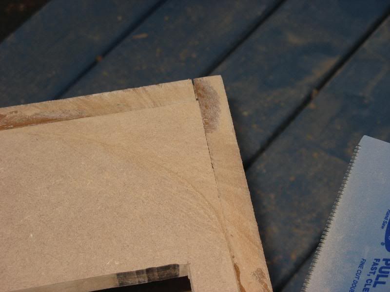
Outer Enclosure: 3/4" MDF Shell with 3/4" MDF 'tiles' overlaying it, forming the Rubik's Squares
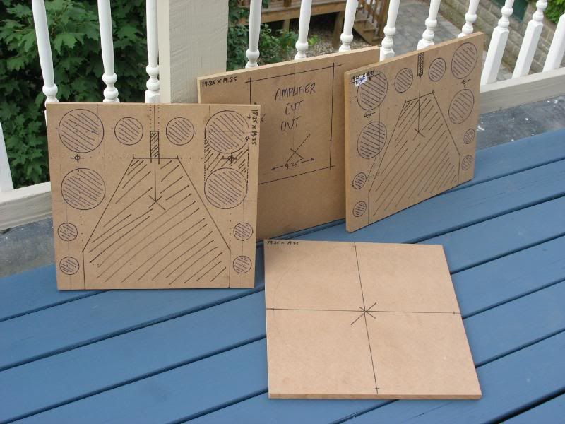
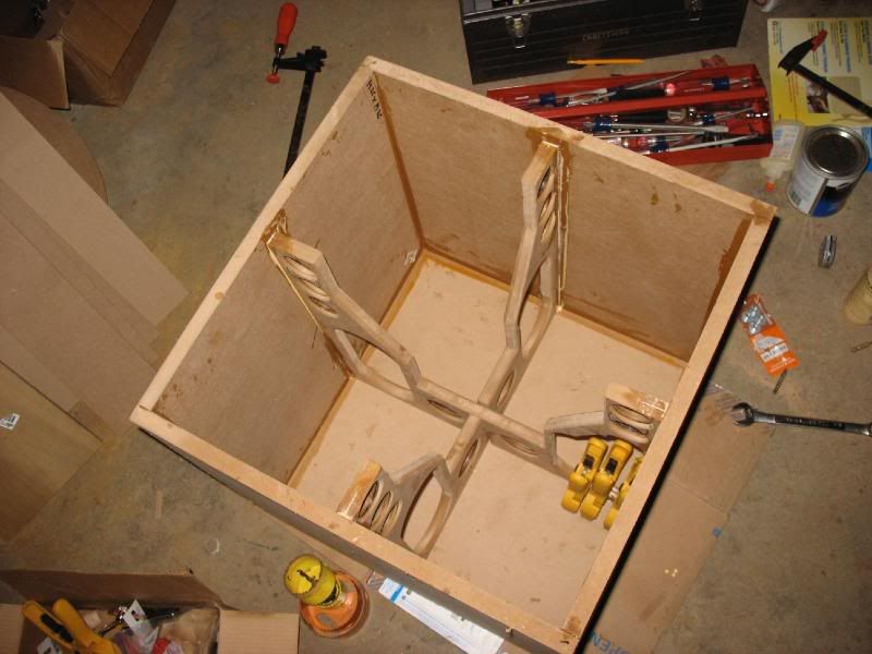
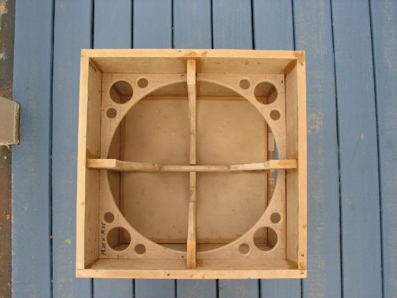
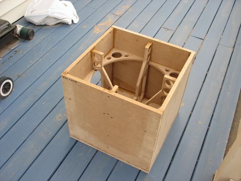
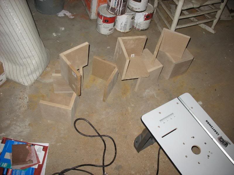
Reinforcement: 1 Y/Z-Axis piece of 3/4" MDF, cut to allow driver. 1 X/Y-Axis piece of 3/4" MDF, cut to allow driver and Plate Amp. 1 Z-Axis piece of 3/4" MDF, cut to allow Driver. 1 full piece of 1/2" MDF at top. 1 Cut piece of 3/4" MDF on bottom.
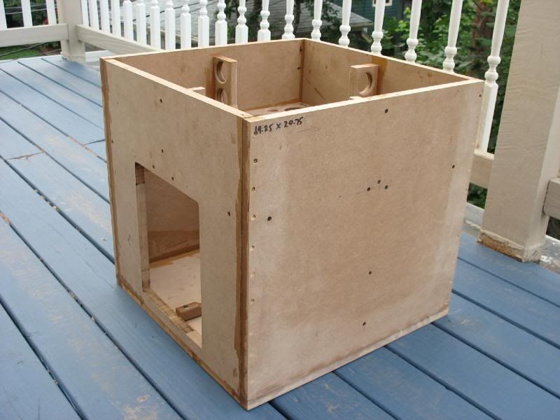
Total Box measurements: 20.75" Wide, 20.75" Tall, 20.75" Long
Tile size: Face: 7.5" X 7.5", Cube: 7.5" X 7.5" X 7.5"
Total Measurements: 22.5" Wide, 25.5" Tall (w/ 3" feet), 22.5" Long
Total Weight w/o Speaker, wiring, Poly-fil, Amplifier: ~98 lbs.
Total Weight: ~144 lbs.
It's a beast, I must say, but before we begin how about some background information? My current system utilizes 2 Paradigm v3.0 Studio 100s (fronts), 1 CC-590 center, and 2 Studio 20s for 5.1 surrounds. Driving all that is an NAD T773, biamped with 2 NAD C272s for the fronts and discrete 7.1 inputs biamping the 20s - Long live the Canadian sound! Likewise, when I finally moved into my new apartment with space for a television (that's a luxury in Boston) I wanted the extra kick for DVDs - what HT is complete without a sub? I'll admit I’m a bit of a purest and can’t stomach the thought of attaching an external sub to my stereo so my search began for something that could rock the 60hz range in movies but neither force me to rewire every time I want to play a CD...
Being a huge fan of my Paradigms, I naturally went to the accompanying model for my Studio 100s - the Direct Servo 15. Despite making a great sub, I also played around with the option I eventually went with - making one. Reasons for this were two-fold - I hadn't taken on any art pieces in a while and just having dropped first, last, security, etc for the new place I didn't want to make a large purchase (insert your Alanis Joke here). Long story short, I chose to go with a Rythmik Audio Servo-15. One visit to Rythmik Audio's website and you can see that these guys aren’t messing around.
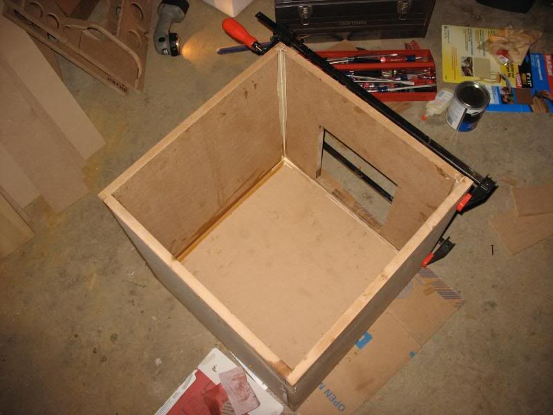
If you're completely new to building (Hi Mom!), here's what you need to know in order to make sense of the pics below: A sealed Sub system (this one) is comprised of air-tight box, a large (usually 8" or more) driver and an amplifier to power it. The driver vibrates the air inside the box which causes low-end sound waves to form. Since the box is being shaken so violently it is extremely important that box be very well braced - as in you should be able to stand on it and jump - it should also be heavy enough that it doesn't move. The interior size of the box is a carefully calculated volume of air that must be present along with the interior support.
So, after 2 weeks of drawing up plans, I finalized my measurements and got started...

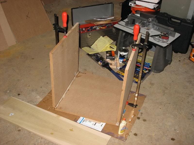
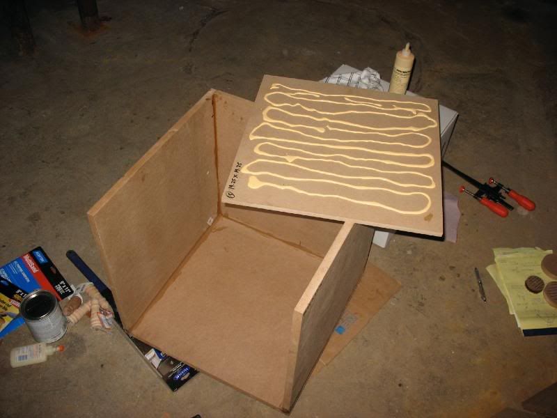
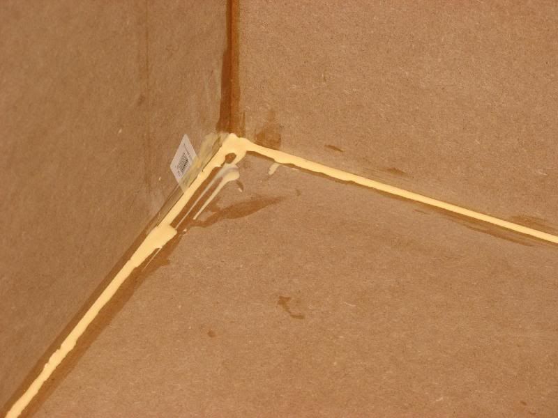
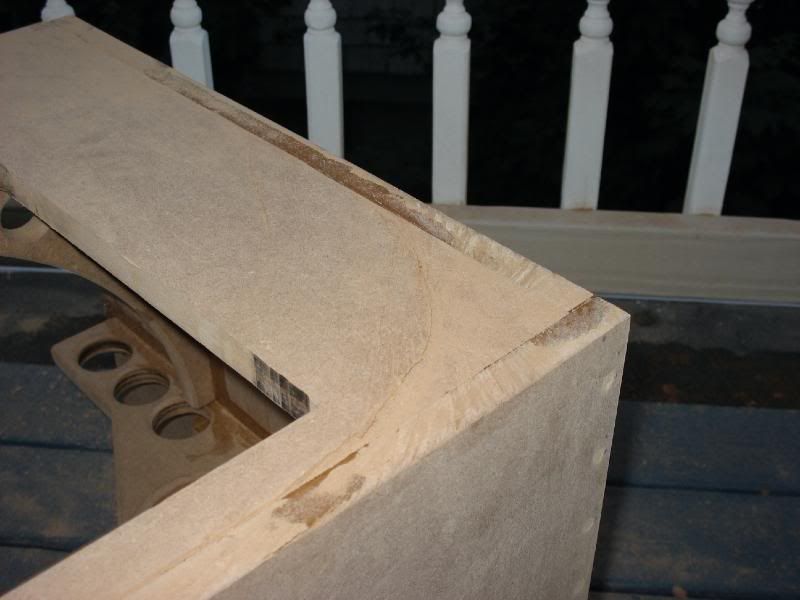
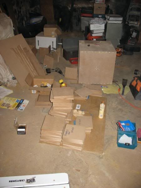
The Glue-Up
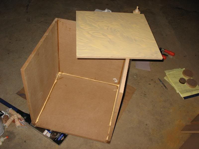
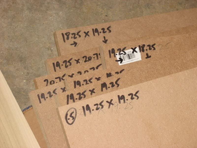
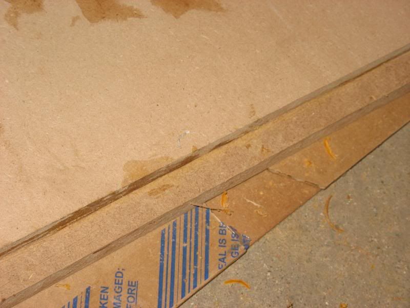
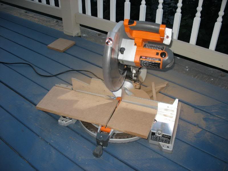
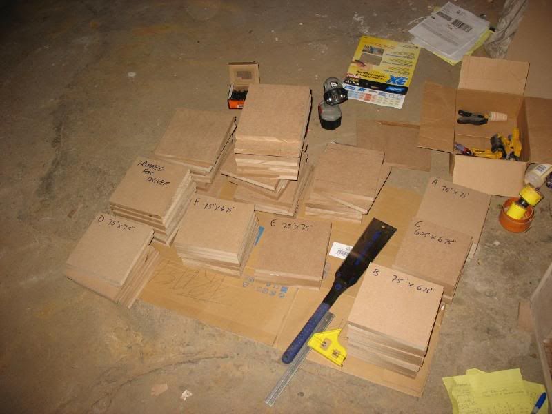
Cutting the Shell


According to the Q equations from Rythmik, I need exactly 3 cu. ft of air surrounding the driver. Here's the math:
Total Interior Box Volume:6762.766"^3
Total Volume of Driver: 871.873"^3
Total Volume of Amp: 406.0625"^3
Total Disposable Air: 5484.8305"^3
V of Tall Brace: 263.484"^3
V of Side Brace: 277.922"^3
V of Tall Brace: 263.484"^3
V of overlap on Side Braces: 2.8125"^3
V of overlap on Tall Braces: 2.25"^3
(-) Necessary 3 Cu. Ft of air: 5184"^3
= -498.9965"^3
So, 498.9965"^3 is the net volume of air that must be displaced, save for the 3 calculations below (the base MDF to be removed from each Brace):
V from Tall Brace 1: 102.75"^3
V of Tall Brace 2: 102.75"^3
V of Side Brace: 190.8517"^3
This brings the total volume of MDF that must be removed (after the initial removal) from the braces to: 102.6448"^3


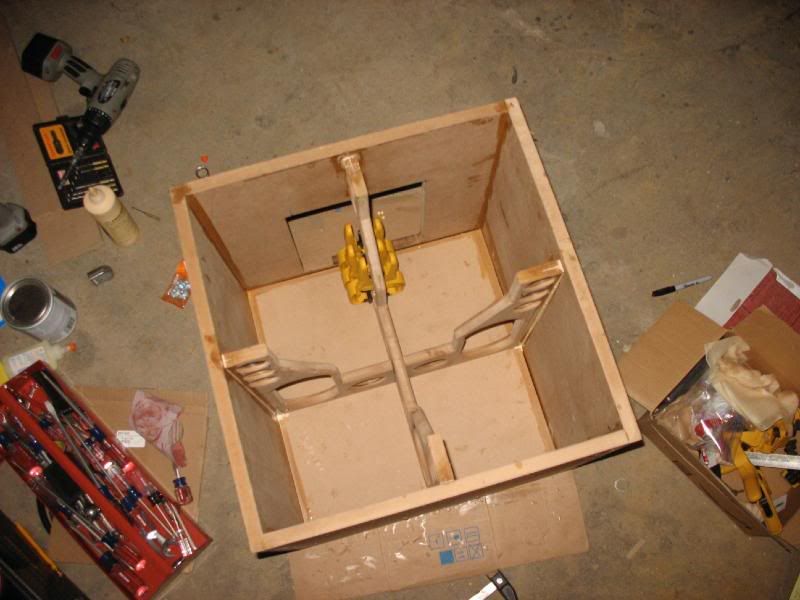
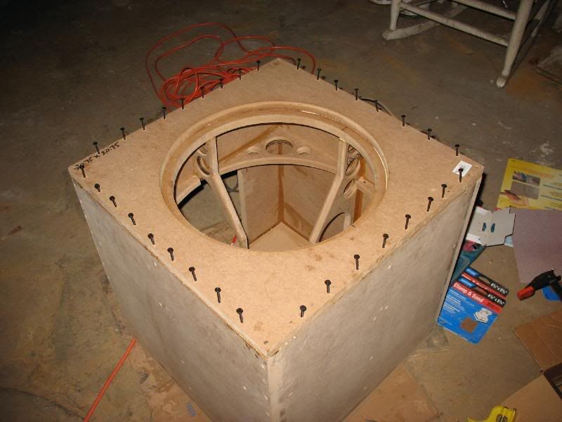
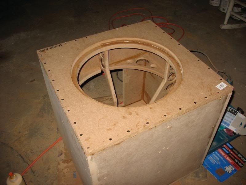
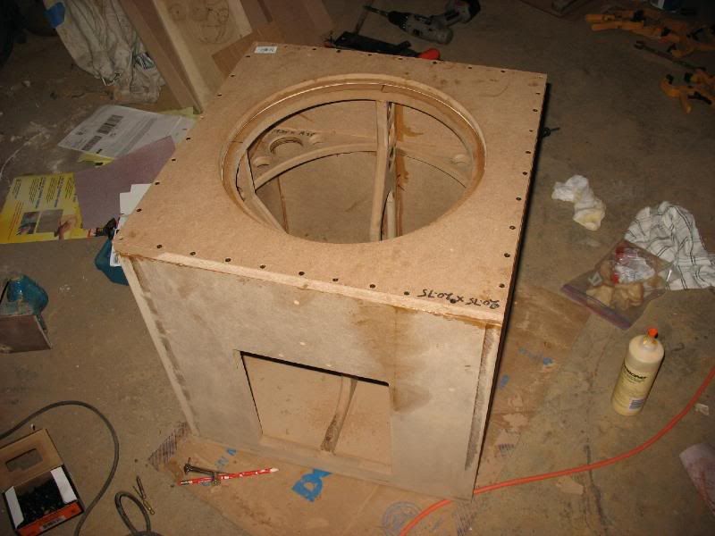
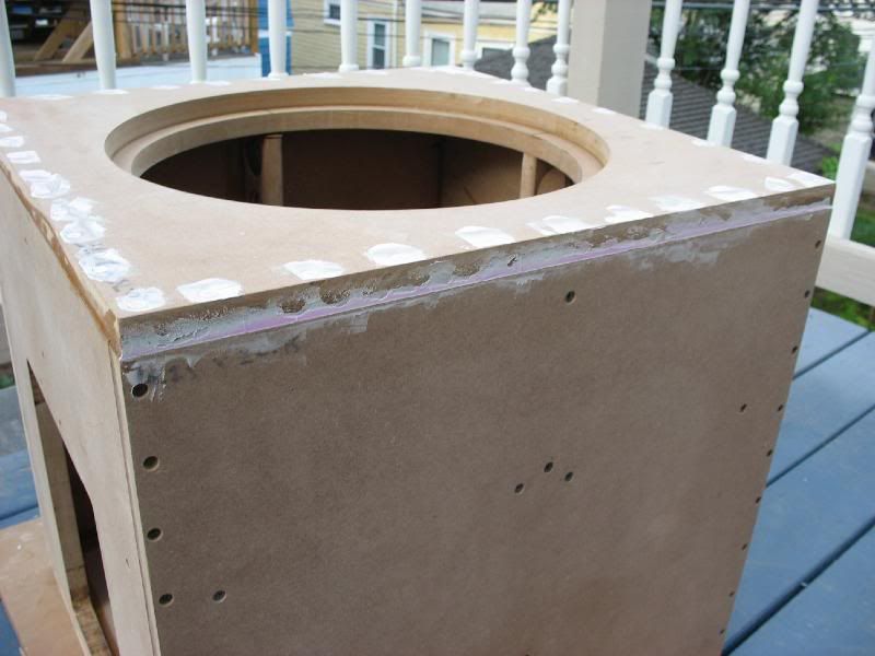
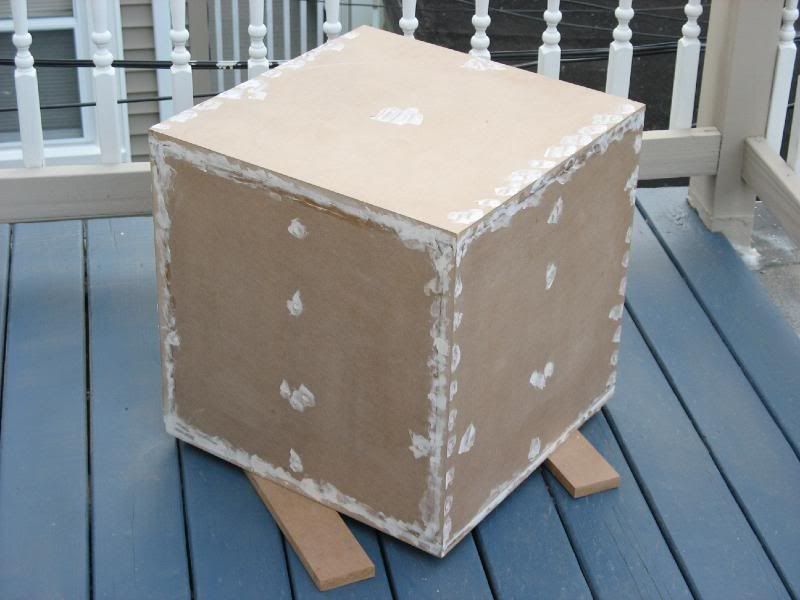
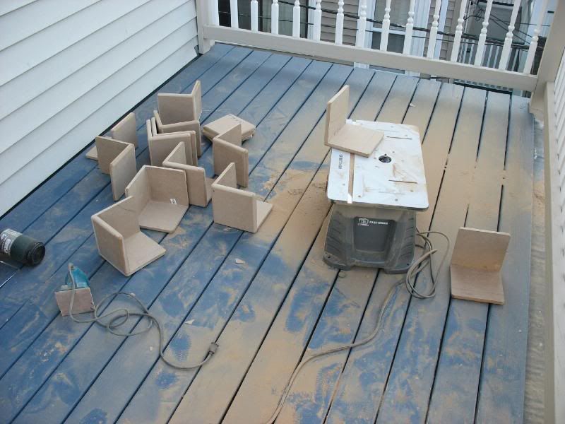
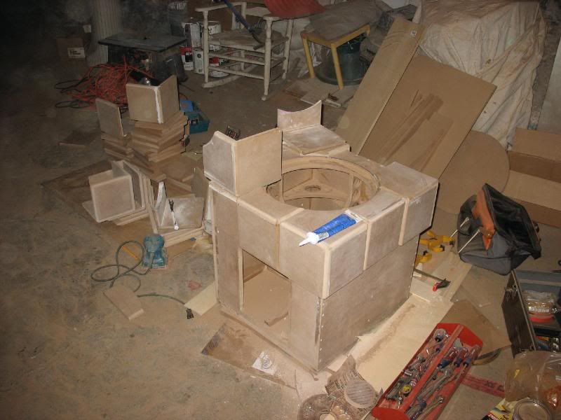
Constructing the Box
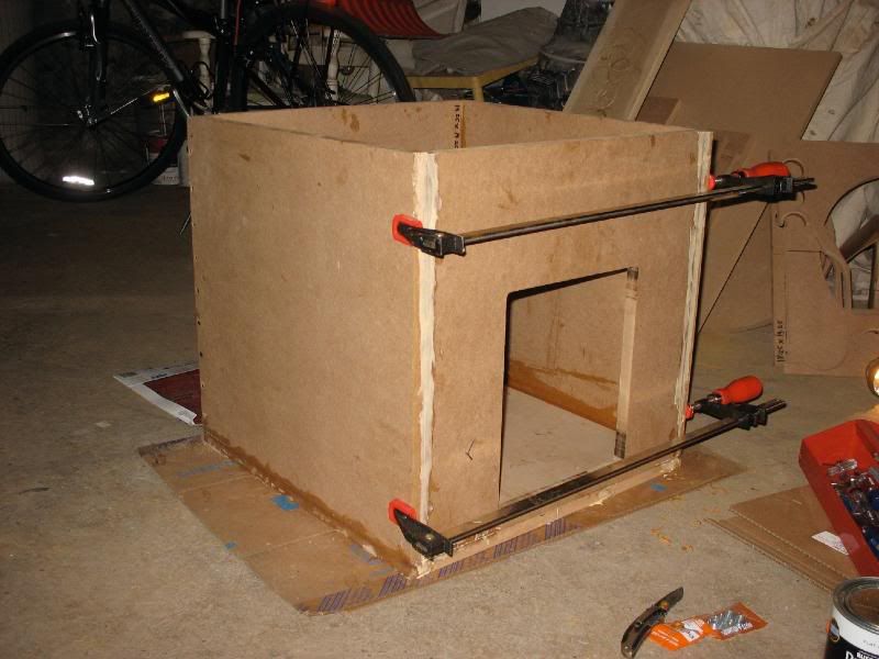
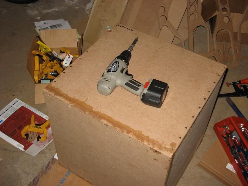
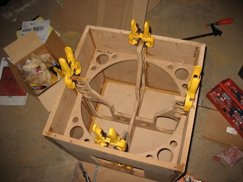
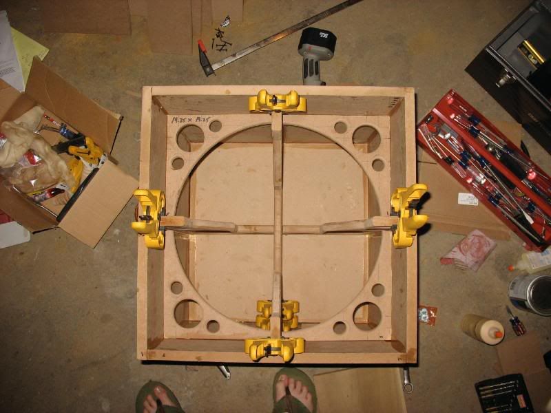
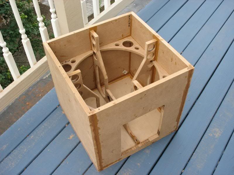
Reinforcing the Box
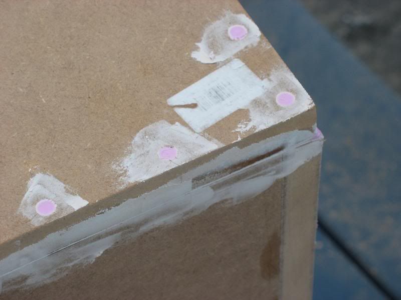
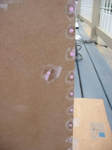
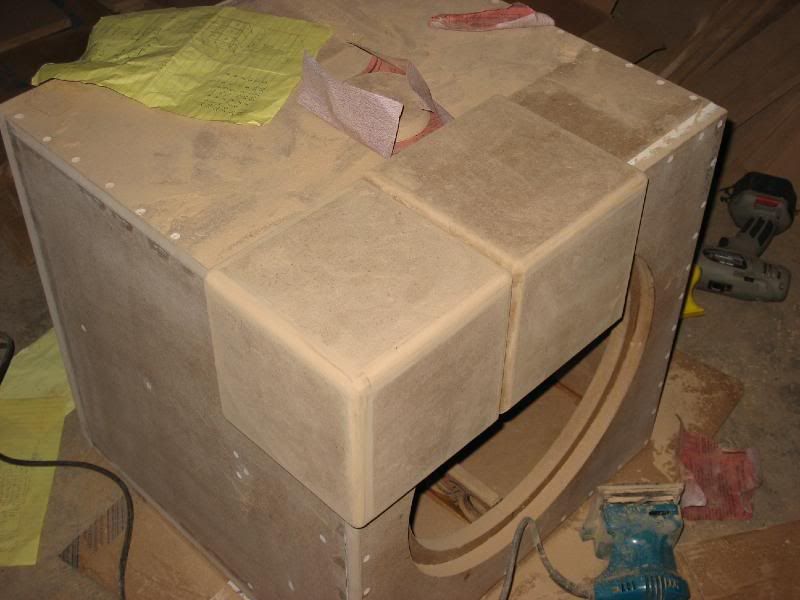
Plastering
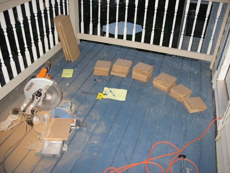
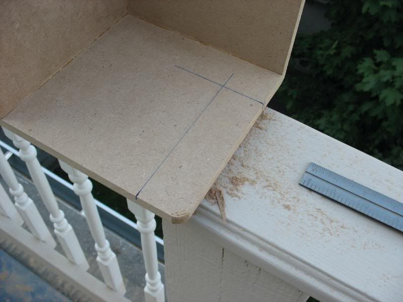
Cutting the Cube...
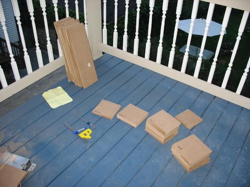
20.75" starting surface + 2(.75") MDF tile thickness = 22.25"
22.25" / 3 Rubik's squares = 7.41667" wide
Since I can't accuarately cut that the larger easier 7.5" dimension is used:
7.5" x 3 = 22.5" - 22.25" = .25" = 1/8" increase on all sides.
Where as adding sheets to the Y/Z/X axis would be the easiest solution, I unfortunately can't obtain 1/8" board!! The other flaw with this method is that it leaves no gap between the squares on each surface - inaccurate to scale.
*PLAN B*
Instead of adding 1/4" to all sides, I instead added 1/4" to each side. This increases the dimensions of the box to 21.25" all around.
7.5" x 3 = 22.5" for the outer dimensions of the bare tiles and (20.75" + 2(.75) + 2(.25)) for the total dimensions leaves .25" for two gaps, or 1/8" gap between all tiles on all sides, fitting the scale.
Problem Solved.
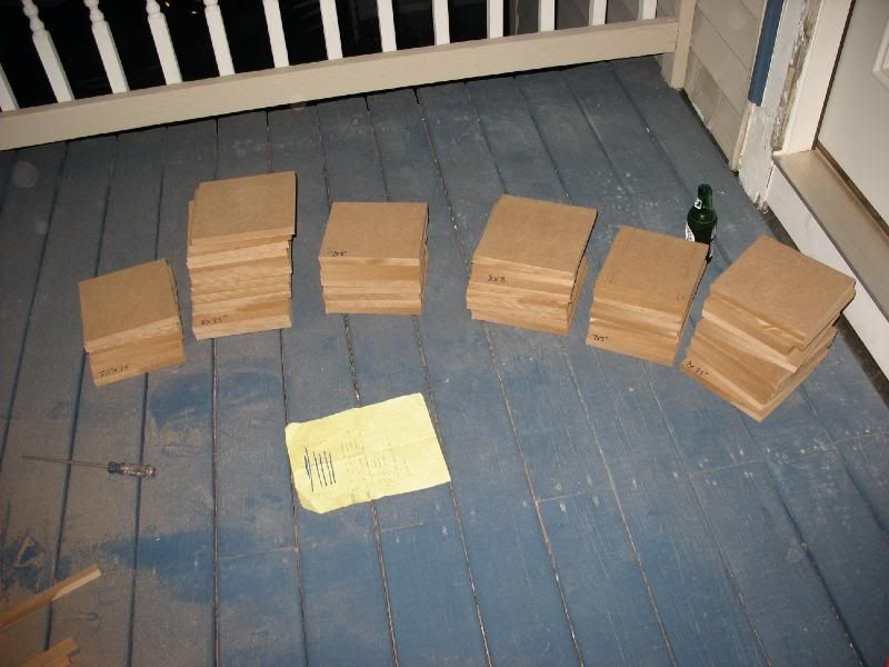
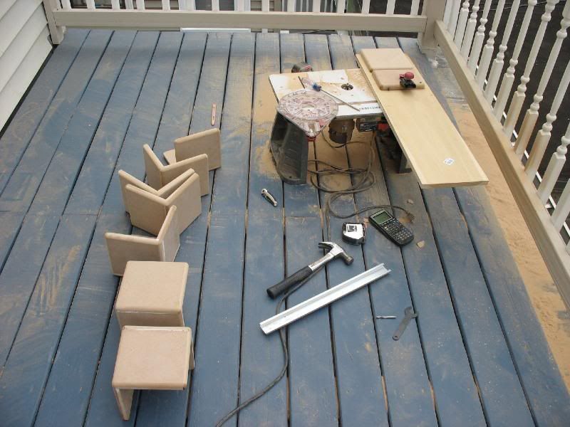
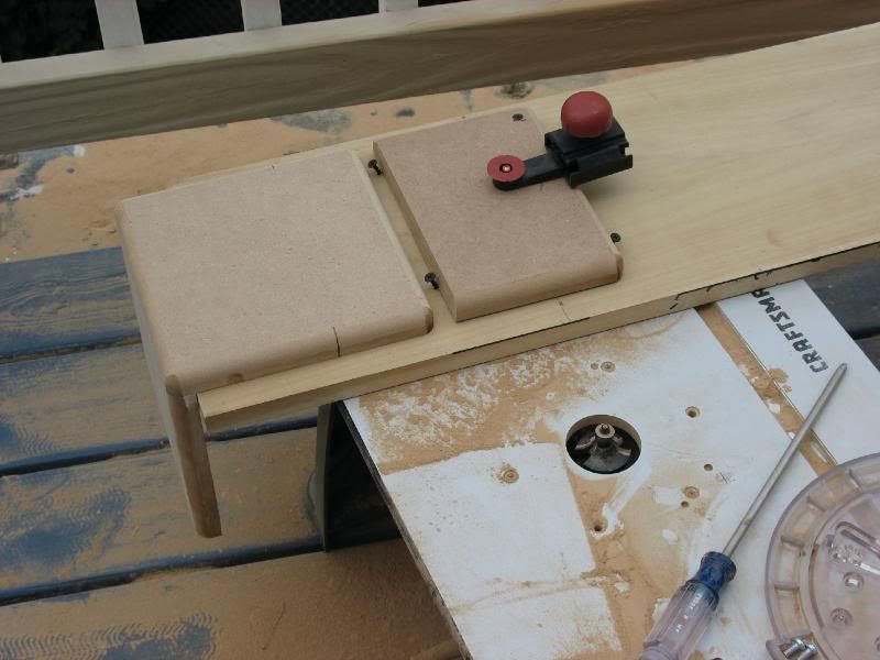
Assembling the Outer Cube
Subscribe to:
Posts (Atom)